AI-assisted development for ATE engineers

The test-engineering loop, closed.

ATE·IQ is a development platform for semiconductor test engineers. It takes the four artefacts every test program lives across — the device spec, the IG-XL test program, the load board, and the production STDF data — and joins them into one traceable, machine-checked loop. AI drafts and explains; deterministic engines verify. Everything runs on the engineer's own machine.

SPEC datasheet · Jama PROGRAM IG-XL · VBT · patterns BOARD schematic · channel map COPPER layout · DRC · fab PRODUCTION STDF · yield · Cpk test_number pin / channel net names PTR / bins lot statistics → proposed limits (never auto-applied) every hop reconciled — a limit, pin or net that drifts is flagged with its owner attributed
Fig. 1 — The closed loop. Each hop is a deterministic join with a named key; the LLM never sits between two pillars.
01

Why it exists

A production test program is never one file. The device limits live in a PDF, the program lives in an Excel workbook, the load board lives at a PCB vendor, and the proof it all worked lives in STDF files nobody opens twice. Every question that matters — does the program match the spec? does the board match the program? which component do I probe when test 1100 fails? — crosses at least two of those silos, and today crosses them by hand.

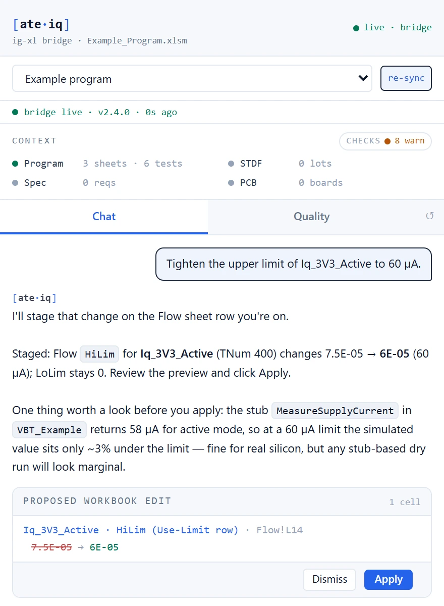
ATE·IQ keeps all four artefacts in one workspace and joins them mechanically: requirements to tests on test_number, tests to board nets on the pin/channel axis, schematic nets to routed copper through a layout binding, program limits to the limits each lot actually ran. The joins are pure functions — same inputs, same answer, every time. AI is used where AI is good: drafting programs, authoring boards, explaining failures — and every AI draft goes back through the deterministic checkers before an engineer sees it.

Those checkers now include the device itself. A generated program is replayed against a model of the DUT — derived automatically from a vendor CMSIS-SVD file or the project's own register map, or your own RTL/SystemC model connected as-is behind a small wire protocol — so semantic errors that compile perfectly, like the wrong register or a compare the silicon can never satisfy, are caught offline instead of on the test floor. Every surface states who judged: your model, or the derived stand-in. What the model cannot judge, it declines out loud.

The platform is grounded in real tester knowledge: a typed registry of UltraFLEX instrument behaviour — envelopes, settle times, prohibitions — authored in our own words with a cited source and a confidence tag on every entry, alongside a working reference programme and 400+ cited ATE load-board design rules. When ATE·IQ makes a claim about an instrument, a settle time or a DIB rule, the claim carries its source.

demo tests traced
34/34
DIB checker rules
164
cited ATE layout rules
400+
board analyzers
9
VBA quality rules
33
automated tests in CI
6,200+
02

Feature guide

Each page below explains one capability end to end — what it does, how it works underneath, and what it looks like on the TMP126 demonstration project.

Test programs

PCB design

Production data & the loop

03

The TMP126 demonstration

Every page in this guide references the same live project: a Texas Instruments TMP126 — a ±0.25 °C digital temperature sensor with a 3-wire SPI interface — taken through the entire loop inside ATE·IQ.

  1. Spec in.

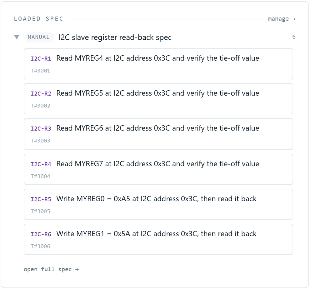
    The TMP126 datasheet becomes 34 structured requirements — DC, SPI protocol, register and temperature-accuracy tests — each with limits, forced conditions and a test number.

  2. Program generated.

    ATE·IQ generates the full IG-XL project: Flow, TestInst, Limits, Binning and Pin Levels sheets, a VBT module implementing all 34 tests, and 24 deterministic SPI pattern files. 100% requirement coverage, all pins attributed.

  3. Board designed.

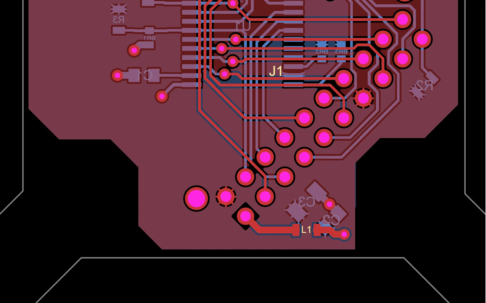
    A five-sheet UltraFLEX-class DIB schematic — DUT, signal conditioning, power, DCVI and digital I/O — with series terminations, Kelvin force/sense, ESD clamps, and routed copper that passes the electrical DRC clean.

  4. Production data joined.

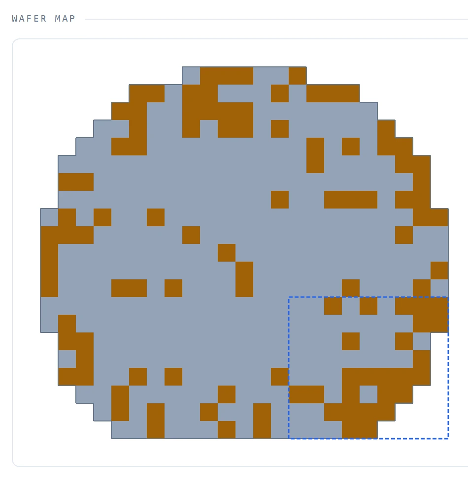
    Wafer-sort and final-test STDF lots parse natively. One test trends toward marginal (Cpk 0.27) and the dashboard names the board components to probe first.

  5. Loop closed.

    The traceability dashboard shows 34 of 34 tests traced end to end — requirement → test → net → copper → lot — with every reconcile green and one documented measurement-path compensation disclosed, not hidden.

Traceability dashboard for the TMP126 demo project
Fig. 2 — The TMP126 project's traceability dashboard: 4 joins, 4 pass, 34/34 tests traced spec → program → copper → production.
04

What ATE·IQ does not do

Three deliberate boundaries, because a verification tool that overstates itself is worse than none. First: offline checks are labelled as offline — final compile authority for a generated program remains IG-XL itself, and ATE·IQ says so rather than claiming tool-correctness it cannot prove. Second: statistics-backed limit proposals are proposals; the tool never silently edits a production limit. Third: when data is missing — no channel plan saved, no STDF ingested, no scan run — the surface says awaiting data and shows the step that unlocks it, instead of rendering an empty chart as if it were a clean one.

05

Talk to us

The useful first conversation is a walkthrough on your device and your tester — a spec you already ship, a workbook you already maintain. Tell us what you are working on and we will reply within one business day.

Contact the team →  ·  [email protected]