Generate
Pattern Generator
Declare an SPI or I²C bus and the transactions you need, and get IG-XL digital patterns, the same pattern in standard interchange and waveform-viewer formats, and a waveform with every cycle labelled. Open a pattern ATE·IQ generated, or paste your Time Sets sheet, and the same viewer shows what drives, what compares and when.
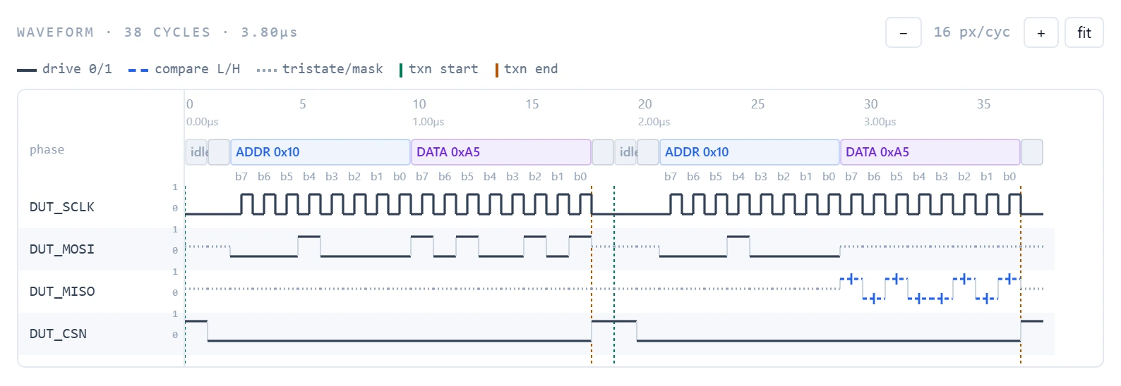
Patterns from the protocol, in four formats
Pick the protocol, map its signals to your pins and list the transactions: by address and data, or by register and field name when a register map is loaded. The generator does the per-cycle transcription, labels every cycle with its phase and bit, and writes all four output formats from one set of vectors.
| Protocol | What you configure |
|---|---|
| SPI | All four CPOL/CPHA modes, MSB- or LSB-first, chip-select framing, compare and masking on the data returned, and a frame built as an ordered list of command, address, dummy and data phases, the way device datasheets describe their transactions. |
| I²C | START and STOP framing, 7- and 10-bit addressing, compare on the slave's ACK, and the master's NACK. |
| Transactions | Reads and writes with ranges and repeats; values in hex, decimal or binary. |
| Output | For |
|---|---|
IG-XL ASCII pattern (.atp) | The tester. |
| STIL | Standard test-pattern interchange. |
| WGL | Waveform-based pattern interchange. |
| VCD | Waveform viewers. |
Open a pattern, paste your Time Sets
The generator is also a viewer for debugging. Select a project and the pattern files stored with it are listed; pick one and it opens as the same labelled waveform, with phase bands, bit labels and transaction boundaries rebuilt from the pattern's own cycle labels, next to the raw pattern text, ready to download. The transaction table fills from the pattern as well, so the pattern you are investigating becomes an editable starting point for the next one.
Paste a Time Sets (Basic) sheet from the workbook and the waveform, and the patterns you generate, follow its drive formats and edges instead of defaults derived from the protocol. When the sheet holds several time sets, the one whose name matches is used, or the first, and the workspace tells you which; when its pins do not match your mapped pins, it tells you that too.
Suites from the register map
Select a project and its register map loads, with its saved bus profile (protocol, frame, pin mapping and time set). Transactions can then be entered by register and field name, and whole suites built in one click:
| Suite | What it builds |
|---|---|
| Reset values | A read of every readable register that has a documented reset value, compared with that value. |
| Walking read/write | A walking-1 write and read-back on every writable bit of each read-write register, with reserved and read-only bits masked, then a clear and a read-back of zero. |
| Read-only protection | A write of the inverted reset value to each read-only register that has a documented reset value, then a read expecting that value unchanged. |
The register map lives on the project. Paste it from a spreadsheet and the columns are detected for you to confirm, or import a CMSIS-SVD file. Save the bus setup back to the project as a named profile and it is there to load the next time the project is selected.
On the demonstration project, a small motion sensor with a 4-wire SPI interface, selecting the project loads its saved profile and register map, and the reset-value suite renders live:
Measured on the demonstration project; the waveform rendered live and nothing was saved to the project.
The waveform is the pattern
The waveform you inspect and the files you download are written from the same vectors, so the preview cannot drift from the output. Solid traces are driven states, dashed traces are compare strobes and dotted traces are tristate or masked. Phase bands carry bit labels, transaction boundaries are marked and the view zooms per cycle. It regenerates as you type, so a wrong clock mode shows up as a wrong waveform, not as a failure at the tester.
Every configuration is checked as it is generated: bit widths, gaps and conflicts in the pin map, reads with no expected value, values out of range and clock rate. Where an IG-XL pattern compiler is configured, the pattern can be compiled from the workspace.