Verify
Device-Model Verification
A program that compiles can still be wrong. It can read a register before the part is ready to answer, compare against a value the part never returns at that point in the flow, or measure supply current in a mode the flow never set. ATE·IQ checks the generated program and its patterns against a model of the device before any tester time is spent. The model is built from the register map you already keep, or it is one you connect from your own side, and every result names the model that judged it.
Compiles is not correct
IG-XL tells you whether a program is valid. It cannot tell you whether the program reads the right register, in the right state, and compares against a value the part can actually return. That question is where test-floor debug time goes, and it is the one a device model answers.
| What a structural check sees | What a device model asks |
|---|---|
| Valid SPI patterns, correct sheet references | Does the command the pattern shifts in form the operation the requirement asked for, on the register it named, or does the part parse it as something else? |
| A well-formed supply-current test with correct limits | Was the part in the power mode the measurement assumes when the meter read, or did the flow never put it there? |
| Read compares populated from the register map | Can the part return that value at that point in the flow, or is the register volatile, so the compare passes or fails by luck? |
| A limit row that validates | Does the value the model predicts for the test land inside that limit, so a wrong limit fails in front of you rather than on the tester? |
A compiler, a schema validator or a lint pass will not see any of these. They are errors of meaning, and ATE·IQ asks about them on generated test programs whenever a model of the device is available. A register map is enough to build one.
Check the program against the device
The model reads what the tester will actually send. Each emitted pattern is decoded bit by bit, the way the part would parse it, without help from the pattern's own comments. Every test then ends in one of three plain outcomes.
It does what was asked
The test performs the operation its requirement named, on the register it named, and the model agrees with every compare.
Expected against actual
A located finding, with the expected and actual values, their units and where in the program the disagreement sits.
Declined, with a reason
The model cannot stand behind an answer, so it says why. A declined check never counts as a pass.
A measurement in the wrong state is a finding
Some measurements mean something only when the part is in a given mode. If the model reports that the flow never set that mode, the measurement is filed as an error before its limits are compared. A read taken too early can return a reset value that sits comfortably inside the limits, and it would otherwise pass. The repair loop may fix the sequencing. It may not delete the measurement, weaken it or widen its limits to make the finding go away.
One verdict, and the program remembers its judge
The model proves itself before it judges: it runs a self-test first, and a failed self-test is never reported as clean, because nothing was verified. A result is clean only when the model and the program's other checks agree. Every result names the model that judged it, and that record stays with the run.
Choose the judge
The model is an input, and ATE·IQ does not invent it. The judge is picked in a fixed order and every surface names it. A model you connect comes first, then a curated model for the part, then one derived from your register map, using a transcribed electrical pack where one exists.
| Judge | What it judges | What it takes |
|---|---|---|
| A model you connect | Whatever your model can answer as the part would. It outranks every other source. | A small adapter on your side (§05) |
| A curated behavioural model | Device behaviour beyond the register map, written clean-room from public documentation, with each behaviour citing its source | Written for one part at a time |
| Derived from your register map | Register behaviour: addressing, reset values, write-then-read-back and the frames on the wire | A register map (§04) |
| Map plus electrical pack | Adds steady-state DC checks such as continuity, leakage and supply current in a declared power mode | A transcribed electrical pack (§04) |
| Electrical pack alone | Pin-level DC checks only | A transcribed electrical pack |
The derived model is the natural place to start. It needs no modelling work, it is ready as soon as a register map lands, and it is the model that judged the demonstration project (§08).
Start from files you already have
You do not need to write a model first. The derived model is built from files the team already keeps.
Import it or paste it
Import a CMSIS-SVD file, or paste a register table from a spreadsheet and confirm the columns ATE·IQ detects. You can edit the map on the project, next to the bus profile the patterns use.
Transcribe the DC figures
Enter the datasheet's DC figures in a guided editor that validates as you type. Each reading keeps its source, and that source appears in any finding that uses it.
If a test depends on something the map does not describe, such as an unmapped address or a read longer than any register, the model declines that compare and names what is missing. It does not guess.
Connect your own model
Connecting the model your design or verification team already runs is a job you can check yourself. Generation is then judged against your model over ATE·IQ's own external-model protocol. The model stays on your side: an adapter you run beside it answers ATE·IQ's questions over the endpoint you register, and the model itself is never handed over.
| In the kit | What it is for |
|---|---|
| Adapter skeletons Python and C++ |
They run straight away against a toy device, so you see the whole loop before changing anything. Then you replace one class with calls into your model. The transport is already written. |
| A cocotb harness | A starting point for a model that is already driven from a simulator testbench |
| The protocol specification | Every question ATE·IQ asks and every answer it accepts, as JSON over HTTP |
| A conformance script Python standard library only |
Runs the same identity, determinism and message-echo checks ATE·IQ applies when it opens your model. It tells you in your own terminal whether your adapter will be accepted, and if not, why. |
On the project page you store the endpoint and a secret, which is encrypted and never shown again. You can probe the connection through the same path generation uses. When ATE·IQ opens a model, the model has to prove itself: it states its identity, a reset must bring back its starting state, and identical questions must get identical answers. A model that fails is refused with the reason on screen. If a model cannot be reached, you see a warning and generation continues on the derived model. A transcript of every exchange is kept with the run, in your own project.
The connection has been exercised on public third-party simulation models: a generic SPI-flash model and an open-source I²C core, running under an HDL simulator.
It declines rather than guesses
A decline is an answer, not a gap. The model says what it cannot stand behind and why, and the report lists every declined test with its reason.
Checksum-protected frames are refused rather than guessed. A register map on its own also declines the part's dynamics, such as conversions, alerts and anything else that changes over time. A curated model or a model you connect adds those. When the model will not vouch for a value, such as the contents of a volatile register, it refuses to fill it in. In the simulator proof build, a refused test is forced to fail so that it cannot pass by luck.
See what the part saw
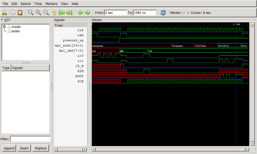
Every pattern-carrying test gets a waveform drawn from the same replay that judged it. It shows the stimulus the tester will drive and the model's response, with mismatches marked cycle by cycle. Below it, a frame table sets what the pattern intended beside what the part parsed.
If a model exposes the part's internal state, that state appears as extra lanes. A derived model shows the bus and the frame table. Fig. 1 shows the idea one level down: a simulator's own raw capture lined up against the tester's pattern.
Run it on IG-XL's offline simulator
The model's predictions travel with the program. IG-XL never runs the model: its offline simulator judges the model's predicted values baked into the program. It runs the program, IG-XL's own flow checks those values against the program's limits test by test, and ATE·IQ reconciles the datalog with the prediction.
Run on simulator can use the IG-XL installation already on the engineer's workstation, or an IG-XL virtual machine. The runs shown on this site used a virtual machine.
The demonstration project uses a small motion sensor with a 4-wire SPI interface. It has a 16-requirement spec and the IG-XL program generated from that spec. The derived model judged it, built from the project's own register map plus a transcribed electrical pack. The model passed its self-test before judging anything, and the replay marked every test clean. The 16 tests produced 25 datalog rows on the offline simulator, because multi-pin tests log one row per pin. Every test agreed with its prediction.
Measured on the demonstration project with the derived model. "Clean" means consistent with the register map and electrical pack as transcribed. Simulator figures come from IG-XL's offline simulator in a proof build: one site, simulated instruments, reads filled from the model.
A clean run proves little on its own. So a second, 7-requirement project on the same device carries defects planted on purpose. On the simulator, a deliberately wrong spec limit failed exactly as predicted. Two reads of volatile registers were refused and forced to fail rather than passing by luck. In all, 3 of 7 tests failed as predicted, and the bin was a FAIL bin. Two checks did two different jobs there. The replay checks the frames on the wire. The wrong limit and the volatile reads were caught by the prediction baked into the program, judged by IG-XL's flow.