Verify
Board Intelligence
Check a load board against the test program before anyone powers it. Open the board and the hub matches its nets to your tester pins, runs a 166-rule DIB check, measures the copper, solves the DC operating point and follows production lots back onto the parts. The same inputs give the same findings, every time.

The analysis hub
One page per board holds every check, computed from the stored design when you open it — never a stale report.
Each card answers a question a DIB review asks. A card that lacks its input says which step unlocks it.
| Card | What it answers |
|---|---|
| Pin match | Does every tester pin in the project's pin map land on a board net? Tolerant of the usual DUT and DIB prefixes and suffixes. |
| DIB check | Does the project's channel map (an ingested Channel Map sheet, or the saved plan when none is ingested) satisfy the 166-rule native DIB checker, and does the board carry the sense nets it declares? |
| Power · rails vs tester config | Every rail with its source, loads and bypass capacitors, checked for eight families of issue and against the tester configuration. |
| DC operating point | What voltage reaches the DUT, which supplies float, where an effective short sits, and whether each pull-up reaches a valid high (§02). |
| Test impact | Which components a test depends on, and which tests a component change would touch. |
| Checks | Copper DRC, electrical errors, connectivity and advisory ATE-shape findings on the board itself (§03). |
| ATE design rules | The built-in load-board design rules that apply to this board (§04). |
| STDF history | Production lots joined onto the board, so a marginal test points at parts (§05). |
| ngspice · KiCad DRC | Second opinions from independent tools, run on demand where those tools are installed (§02, §03). |
Solve the board before it is powered
Every board with a netlist gets a DC operating-point solve before anyone powers it, computed inside ATE·IQ with no SPICE licence, so you know what the DUT will see.
The DUT is stood in by the device's electrical figures from the project. Before it judges your board, the solver proves itself on circuits with known answers, and anything it cannot judge is listed by name rather than left out.
DC operating point
The rail voltage at the DUT, supplies left floating, effective shorts, and whether each open-drain pull-up reaches a valid high level within the pin's sink current. The solved voltages are drawn back onto the schematic, where the parts are.
An independent cross-check
The same extracted netlist, solved by a second engine. It also runs supply-step and pull-up-release transients, sweeps the decoupling network's impedance at the DUT supply, and executes your own SPICE macromodel of the device when you attach one to the project.
Copper, connectivity and a second opinion
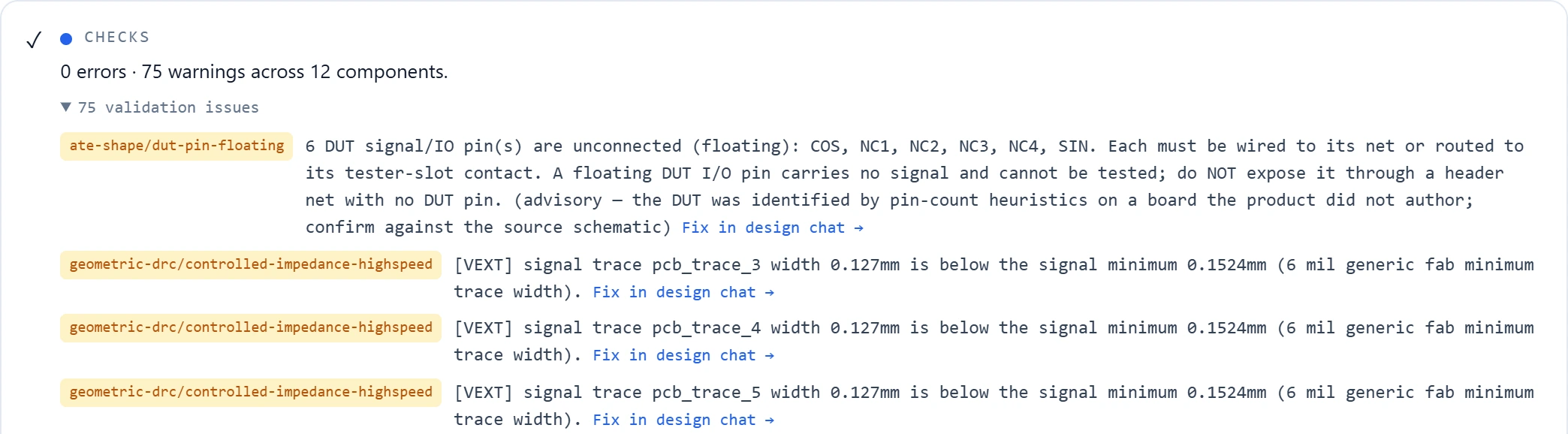
On boards with routed copper, the geometric DRC measures the actual geometry: trace width per net class, pad-to-trace clearance and annular ring. Each finding names its rule and reports the measured value against the threshold, so the fix is quantified before anyone opens a layout tool.
Electrical checks are errors, not warnings: same-layer crossings between traces of different nets, pad encroachment and floating vias. A board that is shorted as drawn cannot pass silently — plausible is not the standard; measured is.
Connectivity is checked as well as geometry: a component with no connections, a net that goes nowhere, a part shorted across a single net. As advisories, the hub also flags DUT pins left floating and signals with no test point.
For a second opinion, where KiCad is installed the board is run through KiCad's own DRC with ATE·IQ's thresholds, and its findings are reported on a card of their own, separate from ATE·IQ's.
Checks that know what a DIB is
The rule content is specific to test hardware. The DIB checker implements a catalogue of 166 rules covering channel assignment, instrument capability and board structure; the Channel Map Designer page describes how it judges a plan. The ATE design rules are built-in load-board design knowledge, each rule carrying a confidence label, so a finding says how firmly the rule is grounded, not just that it fired.
The checkers also know what a DIB is supposed to look like. A Kelvin sense line is recognised as a measurement trace rather than a supply rail, and reported as an info-class note instead of a warning for missing bypass capacitors; a series-terminated signal's tester-side net is followed back to the DUT pin it extends. Neither is flagged for the crime of being correct. A checker that cries wolf on every properly terminated net trains engineers to ignore it.
From a marginal test to a probe point
The STDF history card joins production lots onto the board, and test impact runs in both directions, so a test that trends marginal in production becomes a ranked list of components to probe. The first question at a debug bench is what do I probe? — the hub answers it from data already in the project, before the board is on the bench.
The board checks work in conversation too. Ask the IG-XL agent about a board and it can check a saved design, analyse its nets and power, and look up load-board rules while you work the problem through — in the Excel pane, once you switch it to Debug mode.
Shown on a real board
The pin match and Checks card results on this page come from a real Allegro 17 board, read from its Fabmaster export: 12 components, 23 nets and 68 pins, with real copper — traces, plated holes, vias, and pours drawn as cut with their voids.
Measured on a real, publicly licensed Allegro 17 Fabmaster export, checked against a demonstration pin map in which INDEX is a planted miss.
The DIB-check result on the demonstration project's saved channel plan is shown on the Channel Map Designer page.